Why does a PCB circuit board need impedance, and what is the function of impe...
The "Invisible Rule" of PCB Design: Why Control the Impedance of Circuit Boards?

In the world of electronic product design, engineers often mention a crucial yet somewhat abstract concept – "PCB impedance control." For many beginners or non-professionals, this seems like an esoteric technical detail. We usually understand that wires should be as unobstructed as possible, so why deliberately control a kind of "resistance"? In reality, for high-speed modern electronic devices, impedance control is not optional; it is the lifeline ensuring signal quality, product performance, and even stability.
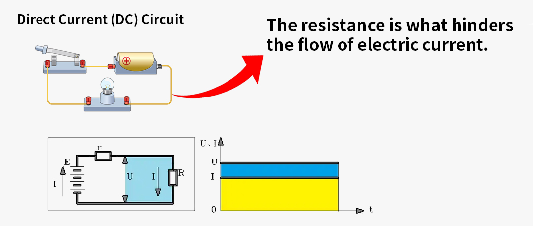
What is Impedance? It's Not Just Resistance
To understand why impedance needs to be controlled, we must first understand what it is. In the world of direct current (DC), what hinders current is resistance (R). But in the world of alternating current (AC) or high-frequency signals (which are essentially rapidly changing AC), the situation becomes more complex. At this point, what hinders current includes not only resistance but also inductive reactance (L) generated by the wire itself and capacitive reactance (C) formed by the wire and its surrounding environment.
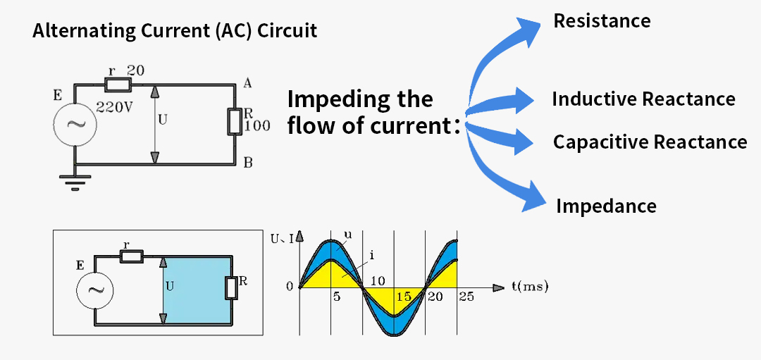
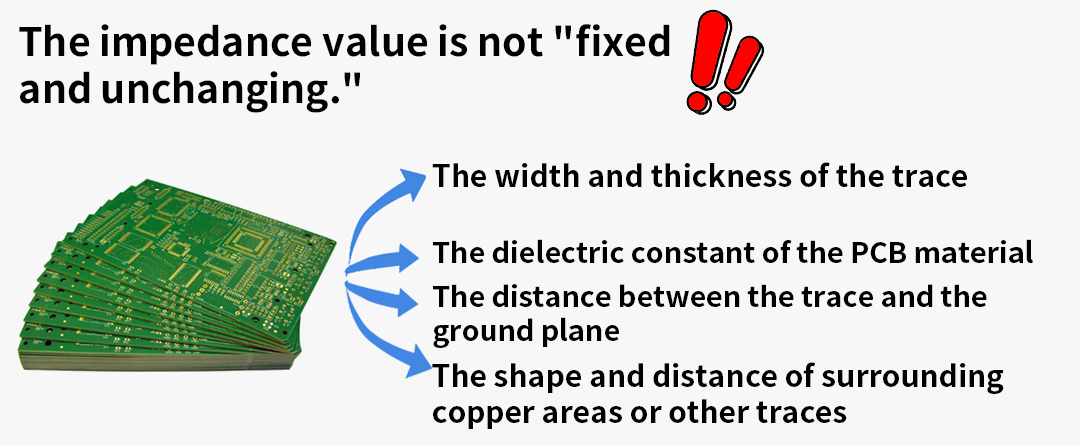
Impedance (Z) is the comprehensive manifestation of these three effects. It can be understood as the "dynamic comprehensive resistance" encountered by a signal on its transmission path. On a PCB, a copper trace is not just a simple wire; it is more like a complex electronic component. Its impedance value is not fixed but is jointly determined by a series of physical parameters, including:
The width and thickness of the trace
The dielectric constant of the PCB substrate material
The distance between the trace and the underlying reference plane (usually the ground plane)
The shape and distance of surrounding copper pours or other traces
Why Strictly Control Impedance? The "Highway Rule" of Signal Transmission
If the signal transmission on a PCB is likened to a fleet of cars driving on a highway, then impedance control is equivalent to setting a unified "lane width" and "road surface standard" for this road. What happens if the standards are inconsistent?

1. Ensure Signal Integrity, Prevent "Traffic Accidents"
When a high-speed signal (such as the data stream of USB 3.0, PCIe, or HDMI) propagates rapidly along a PCB trace, it expects the impedance along the entire path to be continuous and constant. If the impedance value suddenly changes midway (for example, the trace width suddenly changes), an impedance mismatch occurs.
This mismatch, like light refracting and reflecting when passing from air into water, causes a portion of the signal energy to be reflected back to the source. This can have disastrous consequences:
Waveform Distortion: The reflected signal will superimpose with subsequent original signals, causing phenomena like overshoot, undershoot, and ringing at the receiving end – commonly known as glitches and jitter.
Data Errors: When waveform distortion becomes severe enough, the receiving chip will be unable to accurately determine whether the signal represents a "0" or a "1," leading to data transmission errors. This directly manifests as devices not being recognized, blue screens, file corruption, or network packet loss.

2. Reduce Signal Loss, Ensure "Adequate Power"
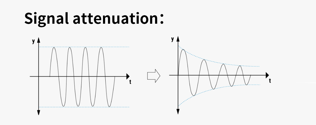
Energy transfer efficiency is maximized when impedance is matched. Imagine water flowing from a thick pipe into a thin pipe; vortices and pressure loss inevitably occur at the interface, causing a drop in water flow energy. Similarly, when a signal passes between paths of different impedance, energy loss occurs, leading to signal amplitude attenuation. In long-distance transmission or radio frequency (RF) signal applications, this loss is particularly fatal, potentially causing the signal to be too weak to recognize by the time it reaches the destination.
3. Improve Circuit Compatibility, Achieve "Standard Docking"
Almost all chip manufacturers, when designing high-speed interfaces, clearly specify the impedance requirements of their pins in their datasheets. This is an industry standard aimed at ensuring compatibility between devices produced by different manufacturers. For example:
High-speed differential signals like USB, HDMI, PCIe typically require PCB traces to provide 90Ω or 100Ω differential impedance.
Single-ended signals like RF antennas, video coaxial cables, universally adopt the 50Ω single-ended impedance standard.
Each address and data line of the DDR memory bus also requires strict impedance control to ensure all data can be read and written synchronously and accurately by the memory chips at extremely high frequencies.
If PCB design does not follow these standards, it will cause "poor communication" between the chip and the circuit board, ranging from degraded performance to the interface being completely non-functional.
4. Avoid Electromagnetic Interference (EMI), Pass "Safety Certifications"
An impedance mismatch point acts like a miniature antenna. Signal energy reflected and scrambled at this point easily radiates outward in the form of electromagnetic waves, forming electromagnetic interference (EMI). This not only interferes with other sensitive circuits inside the device but may also interfere with surrounding electronic devices. This is crucial for whether the product can pass stringent EMC (Electromagnetic Compatibility) certifications.
In summary, PCB impedance control is far from an insignificant design detail. It is like the "lane width" and "speed limit standard" of a highway, building a smooth, unobstructed channel for high-speed signal flow. By precisely controlling the physical parameters of traces to achieve specific impedance values, engineers can minimize signal reflection, reduce energy loss, ensure device compatibility, and suppress electromagnetic interference to the greatest extent.
Therefore, in the fields of high-speed digital and RF design, impedance control is one of the key factors determining the success or failure of a product. It directly relates to the stability, reliability, and performance of the final product.